Trim Chart, Checklists, & Calculators
Aresti |
| |||
Disclaimer: the first two videos are a bit goofy but do a fairly good job of explaining the concepts
Angle of Attack ExplainedVertical Divider
|
|
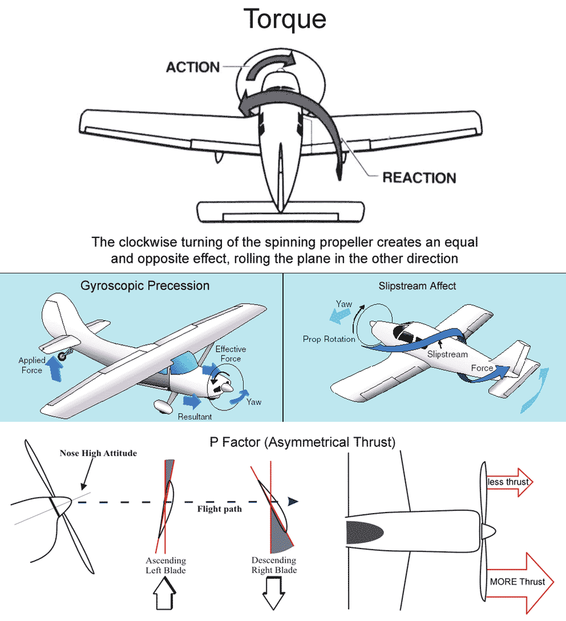
The 4 Left Turning Tendencies